Our Services
Condition Monitoring (Predictive Maintenance) Services
Predictive Maintenance is a process of determining equipment actual status through systematic Condition Monitoring Program (CMP) on periodic or continuous basis.
Modern technology provides a number of methods for determining the condition of equipment or machinery without disassembling or even taking them out of service. Armed with this insight, maintenance needs of equipment are identified and planned in advance based on their actual conditions. Equipment with good operating conditions is left alone for maximum productivity. Maintenance related decisions become more accurate, timely and appropriate. This is basically how one can improve your plant performance while reducing downtime and maintenance costs.
There are various techniques or technologies that can be applied depending on type of equipment/process involved. Some of the technologies that Reliability Monitoring Services can provide are:
• Vibration Analysis
• Infrared Thermography
• Airborne Ultrasound
• Motor Current Signature Analysis
• Field Corrective Maintenance
• Laser Alignment Services
• In House and In Situ Dynamic Balancing (single and two plane balancing)
• Ultrasonic Thickness Gauging
Implementation of Maintenance Technologies
RMS Technical Solutions Sdn Bhd provides implementation services in various maintenance philosophies as mentioned below:
• Total Predictive Maintenance
• Reliability Centred Maintenance
• Maintenance Planning
• Total Shaft Solution
• Root Cause Failure Analysis
Machinery Diagnostics Service
Machinery problem is identified through proper and systematic diagnosis, which includes the following procedures:
Evaluation of machine condition based on ISO and VDI standards by executing vibration related measurements and other parameters (if required). Vibration data analysis for general machine fault(s) identification. Advanced diagnosis such as enveloped vibration analysis, impact test, run up and coast down data recording/analysis, motor current analysis, etc., whichever is applicable and required. Recommendation for the most practical solution(s) of the identified problem(s).
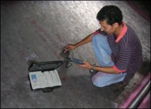
Vibration Analysis
Vibration analysis is a powerful tool for evaluating machine condition assessment and diagnosis in rotating machinery. Without doubt it has proven technology in all industries and from the most important technology element in CBM. Spectral analysis detects changing machine condition well in advance of failure onset. Faults such as imbalance, misalignment, worn belts, and foundation looseness are some of the many faults are detectable. Additional analysis will provide insight motor electrical condition i.e. rotor and stator condition.
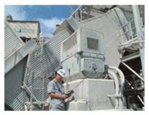
Vibration analysis on rotating machinery
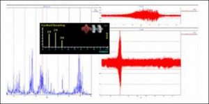
Sample FFT and Time Wave Form
Infrared (IR) Thermography
An IR survey of electrical equipment will identify problems caused by current/resistance relationships. Generally, a hot spot will be generated in an electrical circuit as a result of either a loose, oxidised or corroded connection or a malfunction of the component itself. Measurement is made using a state-of-the-art hand-held thermography camera. This technology is also used in inspecting mechanical equipment.
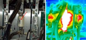
Overheated yellow phase fuse
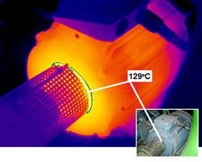
Overheated motor DE bearing
Airborne Ultrasound
An ultrasonic detector senses small changes in the ultrasonic signature of a component and accurately pinpoints potential sources of failure before they cause severe damage to the components. Ultrasonic translators provide information in two ways: “qualitatively,” through their ability to detect ultrasound and convey it through a noise isolating headphone, and “quantitatively” through visual and incremental readings on a meter. Airborne Ultrasound is very useful in Compressed Air Leak Survey, Gas Leak Detection, Steam Traps Survey, Bearing Condition Monitoring, Electrical Inspection, Bearing Lubrication, and Unpressurized Leak Detection.

Motor Current Signature Analysis
This technique diagnose cracked or broken rotor bars, cracked end-ring or high resistance joints in AC induction motors, given that the following conditions are met:
1. Motor is loaded at > 75% of rated full load.
2. Motor is HP rating > 10 HP (7.5 kW)
3. The pole passing frequency (and therefore the running speed) is accurately determined prior to requesting recommendations.
Other Limitations :
Mechanical effects can cause signals similar to rotor defect if the load drive speed is less than 75% rpm. This technique does not diagnose other motor defects such as dynamic or static eccentricity.
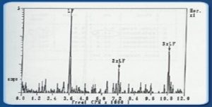
MCSA Spectrum showing dominating of electrical line frequency indicating rotor bar broken or crack.
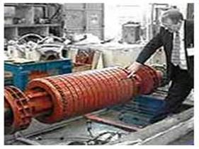
Broken rotor bar
Precision Laser Alignment
Misaligned machines causes: Bearing failure, shaft failure, sealing failure, coupling wear, overheating, energy loss, high vibration etc.
With shaft alignment is meant adjustment of the relative position of two coupled machines, e.g. a motor and pump, so that the center line of the axis will be concentric when the machines are running during normal working conditions.
Measuring with Fixtur-Laser Shaft Alignment Systems means that the system via measuring units mounted on each shaft registers measurement values in three positions. The system calculates and displays the offset value at the coupling, the angular value and the adjustment values for the machine feet on the movable machine.
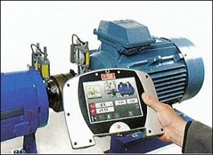
Fixtur Laser alignment system
In Situ Dynamics Balancing
A new black box approach is suggested based on running a minimum number of balancing trials and using regression analysis to relate the vibration amplitude at one or two rotor bearings to the balancing variables (weight, mass and location angle). A powerful optimization technique is used to minimize an objective function combining the vibration levels at both bearings with pre-assigned weighting constants subjected to constraints on the balancing variables. This technique can be applied to both static and dynamic balancing of rigid rotors and a computer program is outlined to facilitate the application of the suggested approach. The preliminary results are encouraging; a reduction in vibration level up to 83.7% has been achieved. Although the approach is applied to rigid rotor balancing problems, it may be of interest in other dynamic problems such as rotors having non-linear support characteristics, fine balancing, variable speed rotors and flexible rotors.
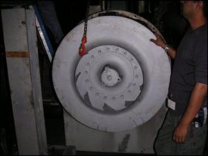
In situ dynamic balancing on fan impeller
Ultrasonic Thickness Gauging
Ultrasonic thickness gauging is a widely used nondestructive test technique for measuring the thickness of a material from one side.
What can be measured Virtually any common engineering material can be measured ultrasonically. Ultrasonic thickness gauges can be set up for metals, plastics, composites, fiberglass, ceramics, and glass. On-line or in-process measurement of extruded plastics and rolled metal is often possible, as is measurement of individual layers or coatings in multilayer fabrications. Liquid levels and biological samples can also be measured. Ultrasonic gauging is always completely nondestructive, with no cutting or sectioning required. Materials that are generally not suited for conventional ultrasonic gauging include wood, paper, concrete, and foam products.